A tolerance tells the machinist how far a dimension may vary and still work. Too loose and parts do not fit; too tight and you pay for precision nobody needs. Here is how our engineers recommend specifying tolerances for CNC machined parts — and what we look for when we review your drawing.
In short
- State one general tolerance standard in the title block (e.g. ISO 2768-mK) and only call out what matters.
- Reserve tight tolerances such as ±0.01 mm for fits, seals and datums.
- Use GD&T when form, orientation or position matter more than size.
- Tolerance and surface finish both drive cost — specify them per feature, not per part.
Why tolerances matter
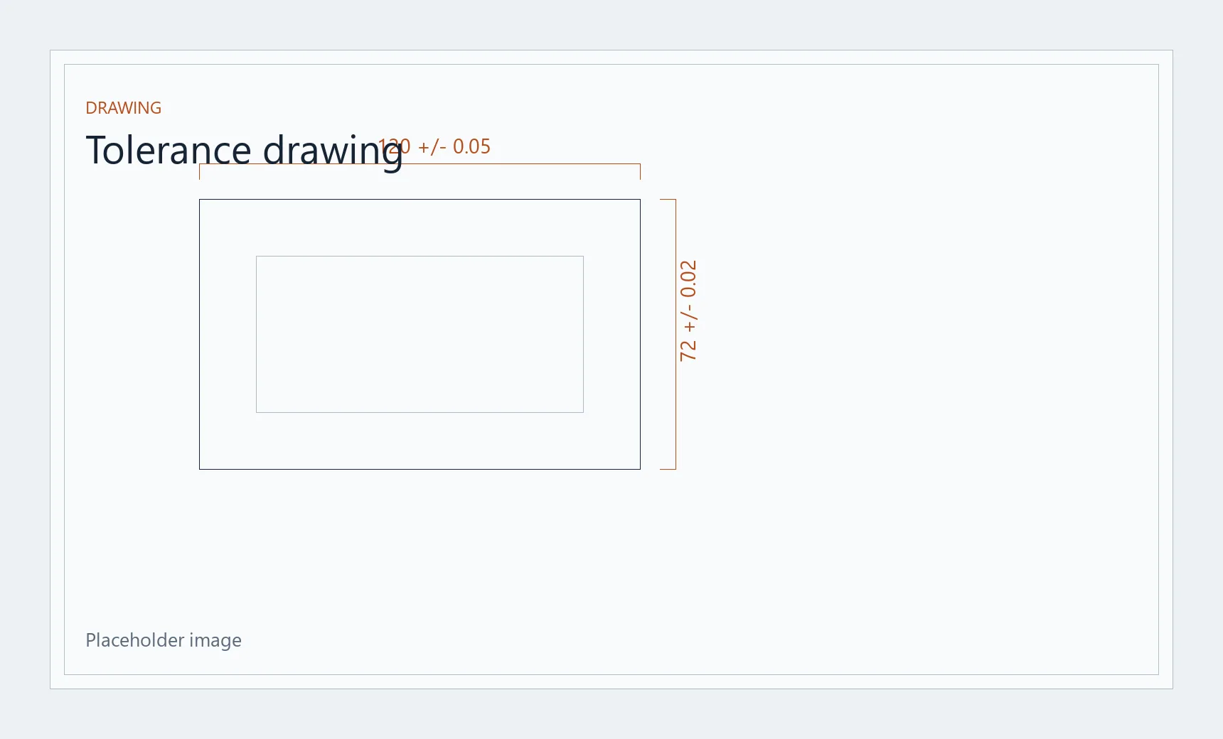
Every dimension on a drawing has a tolerance, written or not. That tolerance decides which machine and tooling we use, how many passes we take, how often the part is measured and how many parts risk being rejected. After material and geometry, it is the biggest single lever on machining cost.
A good drawing separates functional features — the ones that locate, seal, slide or carry load — from everything else. Functional features get explicit tolerances. The rest follow a general standard, so the machinist knows where precision counts and where it does not.
Start with a general tolerance (ISO 2768)
ISO 2768-1 defines general tolerances for linear and angular dimensions that have no individual tolerance, in four classes: f (fine), m (medium), c (coarse) and v (very coarse). ISO 2768-2 does the same for geometrical tolerances such as flatness and perpendicularity, in classes H, K and L. One note in the title block — for example ISO 2768-mK — covers every untoleranced dimension on the sheet.
| Nominal size | f (fine) | m (medium) | c (coarse) |
|---|---|---|---|
| 0.5 – 3 | ±0.05 | ±0.1 | ±0.2 |
| over 3 – 6 | ±0.05 | ±0.1 | ±0.3 |
| over 6 – 30 | ±0.1 | ±0.2 | ±0.5 |
| over 30 – 120 | ±0.15 | ±0.3 | ±0.8 |
| over 120 – 400 | ±0.2 | ±0.5 | ±1.2 |
| over 400 – 1000 | ±0.3 | ±0.8 | ±2 |
For most machined aluminum and steel parts, class m is a sensible default: it sits comfortably within the capability of a modern machining center and needs no special inspection. Use class f when even general features should be tidy — on small precision parts, for example — and keep c for non-critical outlines. If your company works to ASME Y14.5 or uses a title-block rule such as “X.X ±0.2 / X.XX ±0.1”, that works just as well; what matters is that it is stated.
When to call out a tight tolerance
A tight tolerance belongs on a feature only when the function needs it. In practice, that means three kinds of features:
Fits between mating parts
Bearing seats, dowel holes and shaft-to-bore fits. Use ISO 286 fit codes such as H7/g6 (sliding) or H7/p6 (press) rather than plain ± values: they express the intent and let us choose the right tooling and gauges.
Sealing and contact surfaces
O-ring grooves, gasket faces and manifold ports. Here flatness and surface finish usually matter more than size — a perfectly sized face that is not flat will still leak.
Locating features and datums
The holes and faces that position the part in your assembly. Everything else is measured from them, so their accuracy carries through to the whole part.
What we can hold
We hold tolerances down to ±0.01 mm on critical features and check them on our vision measuring system before parts ship; inspection reports are available on request. Each tight tolerance still adds machining and inspection time, so during the DFM review we confirm which features truly need it.
What counts as “tight” also depends on size and material. ±0.01 mm on a 10 mm aluminum bore is a routine finishing pass. The same tolerance across a 300 mm thin-walled part is a different job: aluminum expands roughly 0.007 mm per °C over 300 mm, so temperature and clamping stress can move the part by more than the whole tolerance band.
GD&T basics for machined parts
Plus/minus tolerances control size. Geometric dimensioning and tolerancing (GD&T, defined in ASME Y14.5 and ISO 1101) controls form, orientation and location — which is often what decides whether a part works. The controls we see most on CNC drawings:
- Datums (A, B, C) — the features the part is measured from. Choose the ones that match how the part is assembled.
- Flatness — for sealing faces and mounting surfaces.
- Perpendicularity and parallelism — for faces and bores that must stay square or parallel to a datum.
- Position — for hole patterns. A round tolerance zone around the true position gives about 57% more usable area than the equivalent ± square zone, so more parts pass with the same function.
- Runout — for turned parts that rotate, such as shafts, pulleys and bushings.
Keep it simple: three or four well-chosen geometric controls usually say more than a dozen tight ± dimensions.
Surface finish: specify Ra per feature
Surface roughness is part of the tolerance story. A bore held to size but left rough will wear a seal; a cosmetic face polished for no reason adds cost. Typical values for machined parts:
| Roughness | Typical use | How it is reached |
|---|---|---|
| Ra 3.2 µm | Standard as-machined surfaces, visible tool marks | Normal machining |
| Ra 1.6 µm | Sliding fits, visible cosmetic faces | Finishing pass |
| Ra 0.8 µm | Sealing faces, bearing seats | Fine finishing, sharp tooling |
| Ra 0.4 µm and below | Precision sliding and sealing surfaces | Grinding, polishing or lapping |
Remember that finishes change dimensions. Anodizing builds a layer of a few to several tens of microns, roughly half of it outward from the original surface, and plating adds its own thickness. State whether tolerances apply before or after finishing, and mark threads, bores and fits that must be masked.
How tolerances drive cost
Cost does not grow in a straight line with precision. Going from a general tolerance to ±0.05 mm is usually free on a capable machine. Going to ±0.01 mm can mean an extra finishing pass, slower feeds, temperature-stable conditions, more frequent measurement during the run and a full check of that feature on every part. The main cost drivers:
- Extra operations — finishing passes, reaming, grinding.
- Setups and fixturing — tight relations between features machined in different setups.
- Inspection time — measurement on a CMM or vision system, first-article and final reports.
- Scrap risk — the narrower the band, the more parts fall outside it.
Checklist before you send the drawing
- A general tolerance standard in the title block (e.g. ISO 2768-mK).
- Tight tolerances only on functional features; fits given as ISO 286 codes.
- Datums chosen to match how the part is assembled.
- Surface finish (Ra) per feature, plus the coating and whether tolerances apply before or after it.
- Thread size, class and depth on every tapped hole.
- Material grade and temper, e.g. 6061-T6 or 316L.
- A 3D model (STEP or IGES) together with the 2D PDF — the 2D drawing governs tolerances.
- The quantity, so we choose the right process for a prototype batch or a production run.
How we review your drawing
Every request for quotation goes through a drawing review before we price it. Our engineers check tolerances, datums and finishes against the process, and flag features where a slightly looser tolerance or a different datum would save cost without changing function. You receive the price and this DFM feedback within 24 hours — and you decide what to change.
Have a drawing with tight tolerances?